Bridge Generator
 |
 |
 |
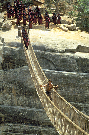
Inspired by the epic rope bridge as seen in "Indiana Jones and the Temple of Doom", I made a simple bridge generator script. The focus of this project was to create a user friendly tool that is flexible enough to work anywhere within a 3D scene. By positioning a couple locators the user can quickly generate a bridge and tweak its appearance using attribute sliders that update in real time. On this page you will find a short video of the script in action and a breakdown of my logic while writing the script.
|
flash content will replace this text
|
Step 1: Create Curves
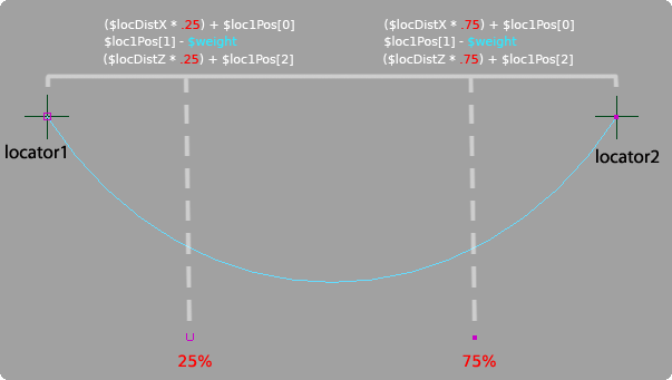
Two locators are used to determine where the bridge will be generated. The positional data of the locators
are stored and used to calculate additional points needed to generate a four point curve. The X and Z values of two new points are
solved by subtracting one locator’s position from the other and then multiplying by .25 and .75 to calculate the
location of the second and third points respectively. A weight value is applied to calculate the Y position of
the new points by subtracting it from the original Y position of the locators. Once all the data is gathered a
four point curve is generated with two control vertices that are influenced by an adjustable weight value.
The original curve is duplicated and offset by a value defined by the used to control the width of the bridge. (Y-Up coordinate system)
 |
Step 2: Divide Curves Into Equal Segments
To plot points along the curve in equal segments I decided to take advantage of the arcLengthDimension node. Bryan Ewert produced and excellent
tutorial on the basic implementation of the arcLengthDimension node and it can be found here. Through his tutorial I was able to place locators along the curve
at equal lengths with any number of segments.
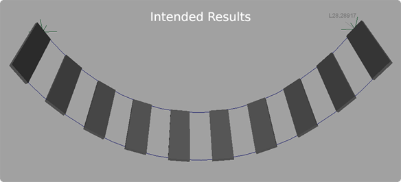
First I needed to find the max U value of the curve and create and arcLengthDimension node based off the maxU. In this example the max U value is 1. The
halfway point of the curve would then be U = .5. When the U value is plugged into the arcLengthDimension node it will return the length of the curve in
centimeters at the set U point. When U = 1 the node returns 28.28917cm, when U = .5 the length is 28.28917cm / 2 = 14.14cm.
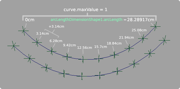 |
Knowing the length of the curve allows me to calculate the size of equal length segments depending on the number of spans the user wants divide the curve into.
In this example, the curve has 10 locators dividing the curve into 9 equal segments. When the script is called to place locators along the curve it takes the
value 10 and subtracts one from it to get the appropriate number of equal segments. The total length of the curve is then divided by that number to get
the size of the segments. 28.28917cm / 9 = 3.14cm.
Now I know the distance in centimeters that each locator should be placed on the curve but I still need to find the U value that correlates to the desired cm value in order to place an object on the curve.
To do this I created a loop that divides the U value in half and measures the midpoint of each division checking to see if it is close to the desired cm value that is
driven by the increment of 3.14. The first locator to be placed next to the origin locator will be at 3.14cm, and the following locator will be at 6.28 and so on.
If the point is before the desired distance then the lesser half of the segment is divided. If the point is after the desired distance the greater half is divided.
This is continually done until a measurement is reached that is incredibly close to the desired point. The epsilon value dictates how close the value must be to be
acceptable; in this case it is set to .0001.
Step 3: Build Planks
To build planks I wrote a new procedure that created geometry at equal segments of the curve instead of using locators. I was able to pull this off quite
simply however the trick was creating planks that followed the positional orientation of the curves. Previously the script was set up for creating planks only along the X axis.
The script had no awareness of what the world orientation of the curves were so I was limited to working only along the X axis. Also, the planks were generated with
their pivot on the original curve instead of being placed in-between the two curves. Not knowing the position of the curves made it difficult to calculate the midpoint
between the curve offset if the curves were not perfectly in line with either the X or Z axis.
 |
It was important I solve the positional awareness of the curves because I already had it set up to create a curve based any configuration of the original locators. As a tool, the artist should be able to use this script without being confined to generating a bridge strictly along the X or Z axis but should be able to create bridges within an established 3D scene.
 |
Another issue was the rotational orientation of the bridge planks. Initially they were oriented to be parallel with the ground instead of following the curve normal. This is solved in "Step 6".
Step 4: Implement Positional Awareness
To solve the problem of creating planks along the curves I decided to take the original curve and align it to the X axis and then perform all my building procedures while I have it in a known coordinate space. After everything is generated I can then group the bridge and rotate it back into place.
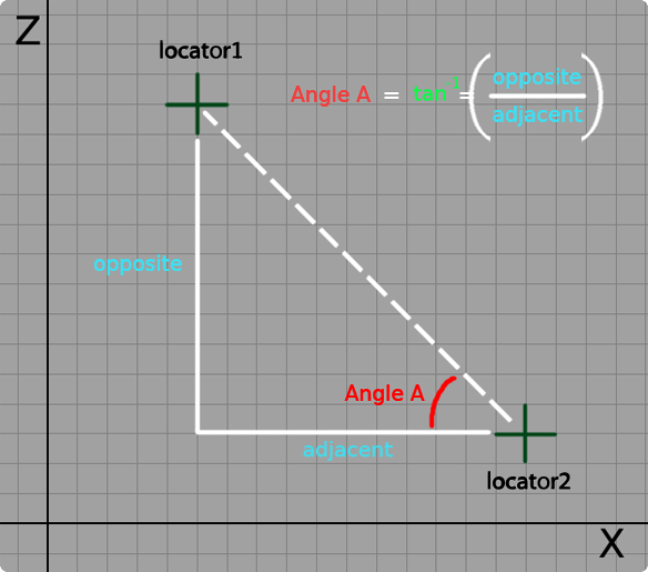 |
A right triangle can be drawn using the positions of the
two locators in the scene. By subtracting the X and Z values of the locators from one another I am able to find the length of the opposite and adjacent sides of the triangle with respect to
the angle I am trying to solve. By using those measurements I am able to solve the inverse tangent which gives me the angle I want. The line of code I used looks like this, atand is
the MEL math function for an inverse tangent: $tanAngle = atand($sideOpp/$sideAdj);
I also implemented if statements to check where the locators are in relation to one another determining if a positive or negative rotation is used with the solved tangent angle.
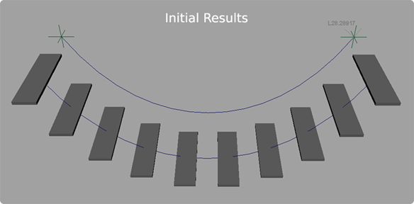
Step 5: Duplicate Curve and Create Planks
Now that I have the curve aligned to the X axis I can begin my build procedures. The first step is to create a second curve and offset it by a certain amount. To start I used an arbitrary value of 5 to test my results. Using Maya's duplicate function a second curve is created from the original and offset along the Z axis.
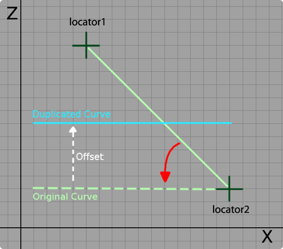 |
The width of the planks are determined by the offset value so they will fill the space between the two curves perfectly. To get the planks generated at the proper location I took the offset value and halved it so that the origin of the plank geometry was placed at the center point between the two curves. I also used the pointOnCurve information from the arcLengthDimension node to derive the Y position of the planks.
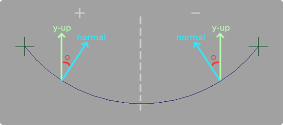
Step 6: Align the Planks to the Curve Normal
The planks are now generated along the curves, however, the next challenge is to get them oriented with the curve normal instead of being parallel with the Y plane. To do this I used a script generated by Malcolm Kesson which solves the rotation necessary to orient any piece of geometry with a surface normal. I was particularly interested in using the script to orient the Y-up of each of my planks with the normal of my curves. To see a complete breakdown of the script, click here, or explore Malcom Kesson's site at www.fundza.com to learn more.
 |
Success! The script worked by feeding in the uParam that I derived earlier from my arcLengthDimension node procedure. Now I just needed to group all the curves and geometry and get it back into the original position. I created a loop that generates a string based on the number of planks requested to be generated. It compiles a string that ends up looking like: select -r plankPoly plankPoly1 plankPoly2 plankPoly3 etc and then appends curve1 and curve2 at the end. The string is used to activate a selection and create a group called bridgeGrp1. Upon creation of bridgeGrp1 its pivot is set to the position of locator2. Next the inverse tangent angle is applied to bridgeGrp1 so all the objects are snapped into their intended position.
Step 7: Create a User Interface
The final step was to create a user interface. Along the development of the script I created variables that allowed me query sliders to attain their values. The interface contains a generate bridge button to initiate the build procedures once the user places two locators into the scene. There is also a delete bridge button that will clear the scene of geometry and curves but will leave behind the locators incase the user wants to continue positioning them.
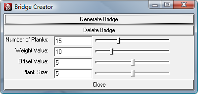 |
The heart of the UI is in the sliders. Weight controls the amount of sag in the curves and the offset value determines how far apart the curves are from one another and how wide the planks are.
The Plank size slider determines how thick the planks are.
Interacting with the UI will update the bridge in real time. To do this I had the bridge completely reconstructed anytime a value change occured. Due to the simplicity of the bridge
Maya is able to quickly regenerate the bridge with smooth results. However, this update procedure would most likely need to be optimized if complex art assets are used instead of simple geometry for planks and curves for ropes.
Final Thoughts
Overall I am pleased with the final outcome of this project. I successfully created a tool that generates a bridge in any coordinate space which was more of a challenge than I originally thought. Getting back to the basics of trigonometry was refreshing and forced me to approach problems with a renewed level of analysis. In the future I want to incorporate an asset loading system that instances art assets where the planks are now. Another idea is to work nCloth dynamics into the bridge so it can be a procedurally animated asset.